
 EN
EN
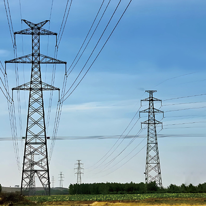
For engineers, contractors, and procurement professionals, understanding tower types is not an academic exercise. It affects foundation design, fabrication schedules, logistics, erection methods, and the long-term maintenance budget of an entire project. This guide breaks down the main types of transmission towers by function, structural form, circuit configuration, and voltage class — and closes with the engineering considerations that determine which type fits a given project.
1. Classification by Function: What the Tower Does on the Line
Every tower on a route has a mechanical job. The simplest way to understand transmission towers is by the load they are built to carry.
1.1 Suspension (Tangent) Towers
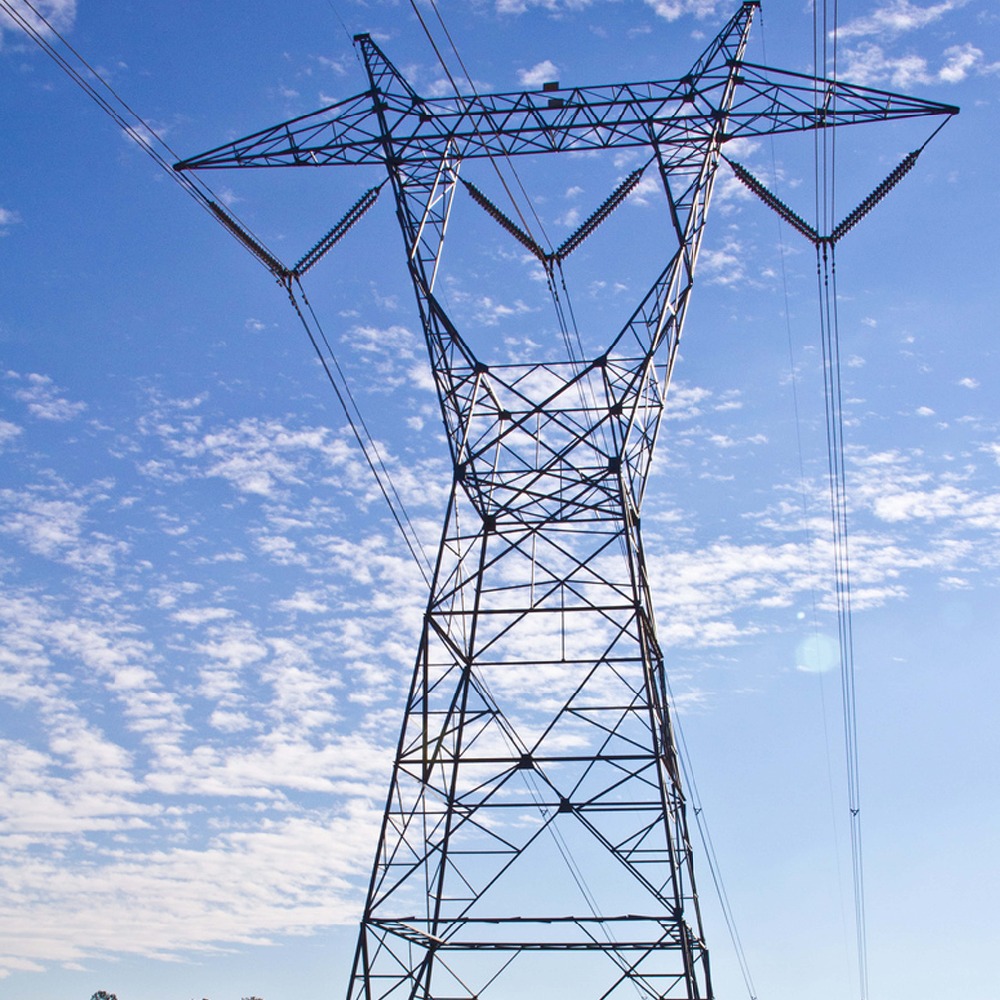
Suspension towers support the conductors on straight sections of the line. Their conductors are suspended from insulator strings that hang freely, allowing the conductors to swing with wind and temperature changes. A suspension tower primarily carries vertical loads — the weight of conductors, insulators, hardware, and ice — plus a limited transverse load from wind. Because their load is comparatively light, suspension towers are the most numerous type on any route, typically accounting for 70 to 80 percent of all towers in a project, and they use the least material.
1.2 Tension (Strain) Towers
Where a line changes direction, or where a long section must be anchored, tension towers take over. Conductors are clamped firmly rather than suspended, so the tower resists the full unbalanced tension of the conductors pulling in opposite directions. Tension towers are also installed at regular intervals — typically every three to five kilometers, depending on terrain — to limit the extent of damage if a conductor breaks. They are heavier, use more steel, and require stronger foundations than suspension towers.
1.3 Terminal Towers
At the point where a line enters a substation or switchyard, a terminal tower provides the transition between the line and the station equipment. One side behaves like a tension tower, anchoring the line conductors; the other side carries the relatively light loads of the station bus work. Terminal towers are critical interfaces, and their design must accommodate the precise geometry of the substation layout.
1.4 Transposition Towers
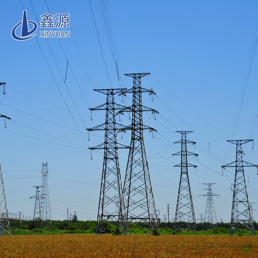
Over long lines, the phases of a three-phase system must periodically swap positions to balance the electrical characteristics of the line. Transposition towers are specially arranged structures where the conductors cross from one side of the tower to the other. These towers have a distinctive configuration and are used at defined intervals along the route.
1.5 Branch Towers
When a line needs to split — one circuit continuing onward and another branching toward a substation or another line — a branch tower (also called a tap tower) handles the junction. Its design combines the functions of suspension and tension support, making it one of the more complex tower types to engineer.
2. Classification by Structural Form
Beyond their function, towers differ fundamentally in how they are built.
2.1 Lattice Steel Towers
The classic lattice tower is an open framework of angle steel sections bolted together into a tapering three-dimensional truss. This open structure offers an excellent strength-to-weight ratio: the triangular bracing resists wind with minimal material, and the open face reduces wind load. Lattice towers dominate high-voltage transmission worldwide because they are economical to fabricate, easy to transport in flat packs, and simple to erect by bolting on site. The entire structure is typically protected by hot-dip galvanizing, which gives the steel a durable zinc coating for decades of service.
2.2 Monopole Towers
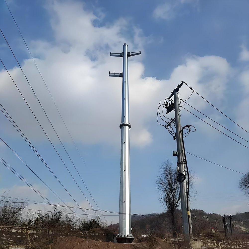
The monopole — a single tapered steel pole, often polygonal in cross-section — is the tower of choice where space is tight. Found in urban areas, near airports, and along congested corridors, monopoles occupy a fraction of the footprint of a lattice tower and have a lower visual impact. They are heavier per meter of height and generally more expensive, but their compactness solves site problems that lattice towers cannot.
2.3 Guyed Towers
A guyed tower is a slender central mast held upright by inclined steel guy wires anchored to the ground. The guys carry most of the lateral loads, so the mast itself can be extremely light. Guyed towers are efficient in open, flat terrain where anchor points are available, and are used for some medium-voltage and long-span applications. Their main constraint is the large area needed for the guy anchors.
2.4 Concrete and Composite Alternatives
In certain regions and applications, prestressed concrete poles and, more recently, fiber-reinforced polymer (FRP) poles appear on lower-voltage lines. Concrete offers long life with minimal maintenance but is heavy and difficult to transport over difficult terrain. FRP poles are lightweight and corrosion-resistant, but remain a niche choice for specific projects, especially in coastal or highly corrosive environments. For high-voltage backbone lines, lattice steel remains the industry workhorse.
3. Classification by Circuit Configuration
The same tower can carry one, two, or more circuits.
3.1 Single-Circuit Towers
A single-circuit tower carries one three-phase set of conductors, typically arranged in a vertical or triangular formation on one or both sides of the tower. It is the simplest configuration and offers the most flexibility in siting, with the narrowest right-of-way for a given voltage.
3.2 Double-Circuit Towers
A double-circuit tower carries two three-phase circuits — six conductors — arranged in a vertical stack on both sides of the tower. Doubling the capacity on a single tower roughly halves the number of towers and the width of the right-of-way compared with two single-circuit lines, at the price of a taller, heavier structure. Double-circuit towers are the standard choice along highways and other constrained corridors where land is expensive.
3.3 Multi-Circuit and Compact Towers
Some projects combine three or more circuits on a single structure, particularly in dense urban and industrial zones. Compact towers, with reduced phase spacing, are another response to right-of-way pressure, although they demand more sophisticated insulators and hardware. Every additional circuit raises the structural complexity and the consequences of failure, which is why multi-circuit towers are engineered with extra care.
4. Classification by Voltage Class
Voltage is the most direct expression of a line's role in the network, and each class imposes its own tower scale.
4.1 Distribution and Subtransmission (35–110 kV)
At these voltages, towers may be lattice or single-pole, with modest heights and light loads. Concrete and wood poles still appear at the lower end. These lines bring power from the transmission backbone to regional networks.
4.2 High Voltage (220–330 kV)
The workhorses of national grids, these lines are predominantly lattice steel towers, with suspension and tension towers alternating along the route. Tower heights commonly range from 30 to 60 meters depending on span and clearance requirements.
4.3 Extra High Voltage (500–750 kV)
EHV lines move bulk power over long distances. Towers grow taller and heavier, with wider cross-arms to maintain the large phase clearances required at these voltages. Foundations become more substantial, and the steel sections are thicker. Some EHV lines use double-circuit configurations to maximize corridor capacity.
4.4 Ultra High Voltage (750 kV AC and above, ±800 kV DC and above)
UHV transmission, including HVDC lines of ±800 kV and beyond, represents the frontier of tower engineering. Towers for UHV lines can exceed 100 meters in height, carry bundled conductors of up to eight sub-conductors per phase, and require some of the largest hot-dip galvanized structures fabricated in the industry. These projects demand manufacturers with proven fabrication capacity, strict quality control, and full compliance with international standards.
5. What Actually Decides the Choice: Engineering and Lifecycle Considerations
Selecting a tower type is a decision about decades of service, and four factors dominate.
5.1 Loads: Wind, Ice, and Conductor Tension
Every tower type is defined by the loads it must survive: extreme wind, ice accretion, and the tension of conductors. Design standards define return-period wind speeds and ice thicknesses for each region, and the tower must remain within allowable stress and deflection limits under these conditions — including broken-conductor cases, where a tension tower must hold the line with one conductor gone. This is why "light" and "heavy" tower types are not interchangeable: substituting a suspension tower where a tension tower belongs invites a cascade failure.
5.2 Terrain and Foundation
Tower type and foundation are designed together. In rocky or mountainous terrain, transport and erection cost may outweigh steel cost, favoring modular lattice sections that can be hauled and assembled by hand. In soft soils, tower weight and base width must be matched to foundation solutions such as concrete pads, piles, or rock anchors. A route survey and soil investigation are prerequisites for any tower selection.
5.3 Corrosion Protection: Hot-Dip Galvanizing and the Fifty-Year Horizon
For steel towers, corrosion is the quiet enemy. A coating failure on a remote tower means costly access for maintenance — or premature replacement. Hot-dip galvanizing remains the industry standard because it protects in two ways: the zinc coating shields the steel, and it sacrifices itself to protect exposed edges and scratches. Properly specified and applied, a hot-dip galvanized coating gives a tower a service life measured in decades, making it the most cost-effective protection strategy across the full life of a line. ASTM A123 and ISO 1461 are the reference specifications for coating thickness and quality.
5.4 Standards as a Floor, Customization as the Ceiling
International standards — IEC, ASTM, ISO, EN — define the minimum requirements for design, materials, fabrication, and coating. Serious projects build on that floor with project-specific customization: non-standard tower heights for special clearance cases, modified cross-arms for unusual conductor bundles, strengthened sections for extreme ice zones, or hot-dip galvanizing specified above the standard minimum thickness for coastal sites. A manufacturer that can engineer and fabricate these variations — not merely reproduce a standard drawing — is the partner a project needs.
5.5 Total Cost of Ownership
The cheapest tower is rarely the most economical. A complete comparison must include fabrication cost, transport, erection, foundation, inspection, and maintenance over a 30- to 50-year horizon. A slightly heavier tower that reduces foundation complexity, or a thicker galvanized coating that pushes back the first maintenance cycle, can return its cost many times over. Procurement professionals who evaluate towers on total cost of ownership — rather than price per tonne alone — consistently achieve better long-term outcomes.
Conclusion
Transmission towers look alike from a distance, but they are a family of highly specialized structures. Suspension towers carry the line; tension, terminal, transposition, and branch towers control it. Lattice steel remains the backbone of the world's grids, while monopoles and guyed towers solve specific site problems. Voltage class sets the scale, and function, terrain, loading, and corrosion protection set the detail.
For every project, the right tower type is the one that balances structural integrity, site conditions, and lifecycle cost — designed to standards, and customized to reality. That balance is what keeps power flowing reliably for the next fifty years.